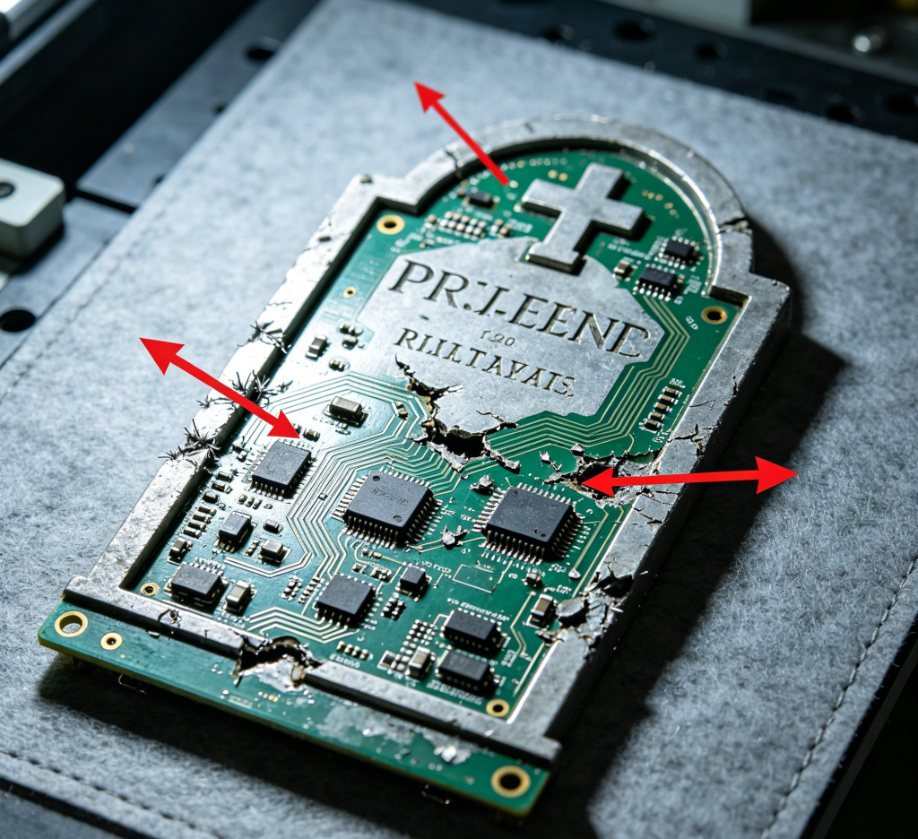
PCBA Defects That Will Ruin Your Day (And How to Stop Them)
You design a board. You send it to the factory. You wait three weeks. The boards arrive.
You plug one in… and nothing happens.
Or worse – it works for five minutes, then a puff of smoke comes out of a tiny capacitor, and you spend the next two days with a multimeter and a microscope, trying to figure out what went wrong.
I’ve been there. Most hardware people have.
The good news is, most PCBA defects follow the same patterns. Once you know what to look for, you can spot them early – or better, stop them from happening at all.
Here are five defects I’ve seen more times than I’d like to count, and what actually causes them.
- Tombstoning – When a Tiny Part Stands Up Like a Gravestone
What it looks like
A small capacitor or resistor (usually 0402 or 0201 size) is standing on one end, not soldered flat. One side is attached, the other is pointing up in the air. It looks like a tiny headstone.
What actually happened
During reflow, one end of the component heated up and melted its solder before the other end. Surface tension pulled the part upright.
Why it happens
Uneven copper pads under the part – one side connects to a big copper pour (heats slower), the other to a thin trace (heats faster)
Poor solder paste printing – more paste on one side than the other
The part is too small for the pad design
How to avoid it
Make sure both pads have similar thermal mass (add thermal relief spokes if one side connects to a ground plane)
Check your paste stencil design – keep paste volumes balanced
If you’re using 0402 or smaller, ask your CM about their tombstone experience. Some machines handle them fine, some don’t.
Real story
A customer once had 30% tombstoning on a batch of 500 boards. They blamed the assembly house. We looked at the layout – one pad had a thermal relief, the other was solid copper. Fixed the design, next batch had zero tombstones. Cost them nothing to fix, but they wasted weeks of troubleshooting.
- Solder Bridges – When Solder Connects Things That Shouldn’t Touch
What it looks like
A blob of solder shorts two adjacent pins – usually on fine‑pitch ICs like QFPs or connectors. Sometimes it’s obvious. Sometimes it’s a tiny hair of solder you can only see with a magnifying glass.
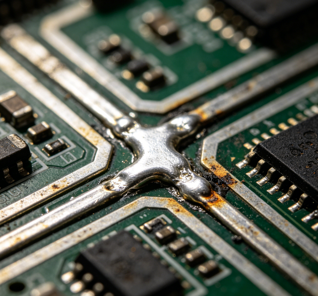
What actually happened
Too much solder paste deposited between two pins. During reflow, the paste melted and flowed sideways, connecting the pads.
Why it happens
Stencil apertures are too large or too close together
Stencil is too thick for the pin pitch
Solder paste is old or has poor slump resistance (it spreads before reflow)
The pick‑and‑place machine misaligned the part slightly
How to avoid it
Use a thinner stencil for fine‑pitch parts (0.1mm or 0.12mm instead of 0.15mm)
Reduce the aperture size or use “home plate” shaped openings instead of full rectangles
Ask your CM to run a solder paste inspection (SPI) – it catches bridges before reflow
Real story
A 0.5mm pitch connector kept bridging on one customer’s board. The assembly house tried everything – different paste, different oven profile. Finally we reduced the stencil aperture width by 15% and the bridges disappeared. Such a small change, but it made all the difference.
- Insufficient Solder – A Weak Joint Waiting to Fail
What it looks like
The solder doesn’t fully wet the pad or the component lead. You’ll see a dull, grainy surface, or the solder looks like a ball sitting on top of the pad instead of spreading out.

What actually happened
Not enough solder paste, or the paste didn’t melt properly.
Why it happens
Stencil is too thin or apertures are too small
Paste was old or dried out
The board surface finish is contaminated (oxidation on ENIG or HASL)
Reflow temperature was too low or too short
How to avoid it
Ask your CM for solder paste thickness data – typical target is 0.1mm to 0.15mm after printing
If using ENIG (gold) finish, make sure the factory stores boards properly before assembly. Gold doesn’t oxidize much, but the nickel underneath can.
For HASL (hot air leveling), be extra careful – the surface can be uneven and cause poor paste release
Why this one scares me
Insufficient solder joints often pass electrical test at the factory. They fail later – after thermal cycling, vibration, or just time. A weak joint can work for weeks before it cracks. That’s the worst kind of defect to debug.
- Solder Balls – Little Metal Spheres Loose on the Board
What it looks like
Small, round balls of solder scattered around component legs, usually near passive parts. Sometimes they’re stuck to the board, sometimes they roll around freely.

What actually happened
Solder paste splattered during reflow, or excess paste got squeezed out from under the component.
Why it happens
Paste was too wet or had too much flux activity
The stencil was misaligned, causing paste to print outside the pads
The board absorbed moisture before reflow (popcorning effect)
Reflow profile ramped up temperature too fast
Why it’s bad
Solder balls can roll around and eventually short two pads or pins. I’ve seen a board fail intermittently because a tiny solder ball got stuck under a connector after shipping. Took days to find.
How to avoid it
Proper reflow profile – slow ramp rate (1‑2°C per second)
Dry the PCB before assembly if it’s been sitting for a while (especially for moisture‑sensitive boards)
Check stencil alignment and cleanliness
Quick test
If you see solder balls, ask your CM for their reflow profile. A good profile has a “soak zone” that allows volatiles to evaporate slowly before the solder melts.
- Component Shift or Skew – Parts That Look Drunk
What it looks like
A chip or resistor is rotated slightly on its pads, or it’s sitting off‑center. Sometimes it’s just a few degrees. Sometimes it’s so bad that leads don’t even touch the pads.
What actually happened
The component moved between placement and soldering.
Why it happens
Poor board support in the reflow oven – the board warped and the part slid
The pick‑and‑place machine placed it slightly off, and the solder paste didn’t have enough surface tension to pull it straight
Board vibration during reflow (conveyor jitter)
Uneven heating in the oven
How to avoid it
Good fiducial marks on your PCB – essential for accurate placement
Ask your CM about their reflow oven conveyor and board support system
For large or heavy components, consider gluing them before reflow (though most boards don’t need this)
When it’s okay
Minor skew is fine if the leads still align with pads. But if leads are off by more than 25% of the pad width, you risk poor soldering or shorts.
Real story
I saw a batch where every Bluetooth module was rotated by about 10 degrees. The boards still worked, but the customer rejected them because they looked sloppy. The factory had to rework all 1000 boards at their own cost. The cause? A worn‑out conveyor belt in the oven that shook the boards slightly during heating. Replaced the belt, problem solved.
Bonus: How to Catch These Before It’s Too Late
You don’t need to be a factory expert to prevent most defects. Just do these three things before you click “order”:
Get a DFM (Design for Manufacturing) review
A good CM will run your Gerber files through software that flags tombstone risks, insufficient annular rings, solder bridge risks, and more. If your factory doesn’t offer DFM, find another.
Ask about their inspection steps
Do they have SPI (solder paste inspection)? AOI (automated optical inspection)? X‑ray for BGAs? If they say “we eyeball it,” walk away.
Build a small test batch
Even 10 boards can reveal tombstoning, bridges, or alignment issues. Fix the design before you run 10,000.
Final Thoughts
Defects happen. Even the best factories have bad days. But most defects are predictable, preventable, and often caused by design choices you can fix for free.
The real cost isn’t the solder balls or the tombstones. It’s the time you spend troubleshooting, the shipments you delay, and the customers you disappoint.
So next time you send a board to assembly, think like the person running the reflow oven. Give them balanced pads, clear fiducials, and a design that doesn’t fight the process.
They’ll thank you. And your boards will actually work.